
Introduction
Today marks the start of a new side project here at 4WDaus — the restoration of a British Ericsson 35MW (later converted to 235MW) wall telephone. This particular unit was installed by the PMG NSW and remained in service until the 1970s before spending decades in storage.
The restoration project begins with a classic piece of Australian telecommunications history: a British‑built Ericsson 35MW, later converted to the 235MW handset model and installed by the Postmaster‑General’s Department (PMG) — the federal authority responsible for all postal, telegraph, and telephone services from 1901 until 1975. As Australia’s national communications provider, the PMG standardised equipment across the country, and from around 1919–1920 adopted the British Ericsson Model N2500 as the Telephone No. 35MW, deploying thousands throughout rural NSW. This particular unit served in Inverell, NSW, where magneto wall sets remained in operation well into the 1960s and early 1970s. Many 35MW instruments were later upgraded to 235MW models by PMG workshops, replacing the fixed transmitter with a handset and covering the original mounting holes using a horizontally mounted “To Call” instruction plate — a conversion method characteristic of PMG NSW and visible on this example. Constructed in oak or walnut and powered by a four‑magnet generator, the Ericsson magneto telephones earned a reputation for reliability, making them a mainstay of regional Australian communications for more than half a century.
With good lighting and a careful first inspection, the initial condition is surprisingly solid for a device of its age. Below is the first photographic record and the baseline assessment before restoration begins.
Initial Condition Assessment
Although the phone presents well, several issues will need attention:
- Back Plate Screws Missing
Ten slotted screws are absent from the rear plate. These must be replaced with correct slotted head screws, not Phillips.
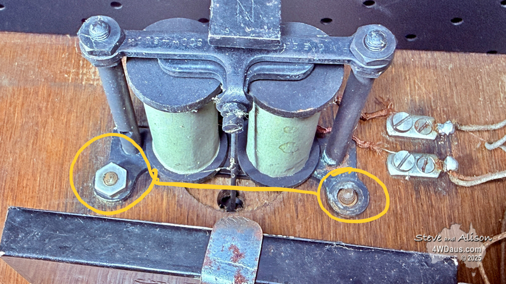
- Bell Assembly Issue
One brass bell is missing the six‑sided nut that secures the bell post.
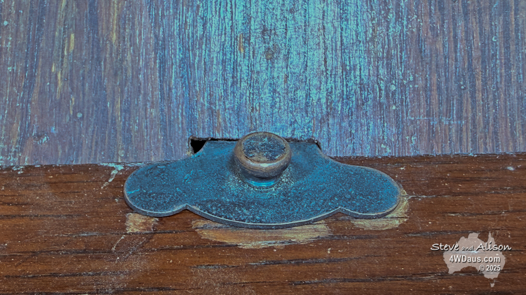
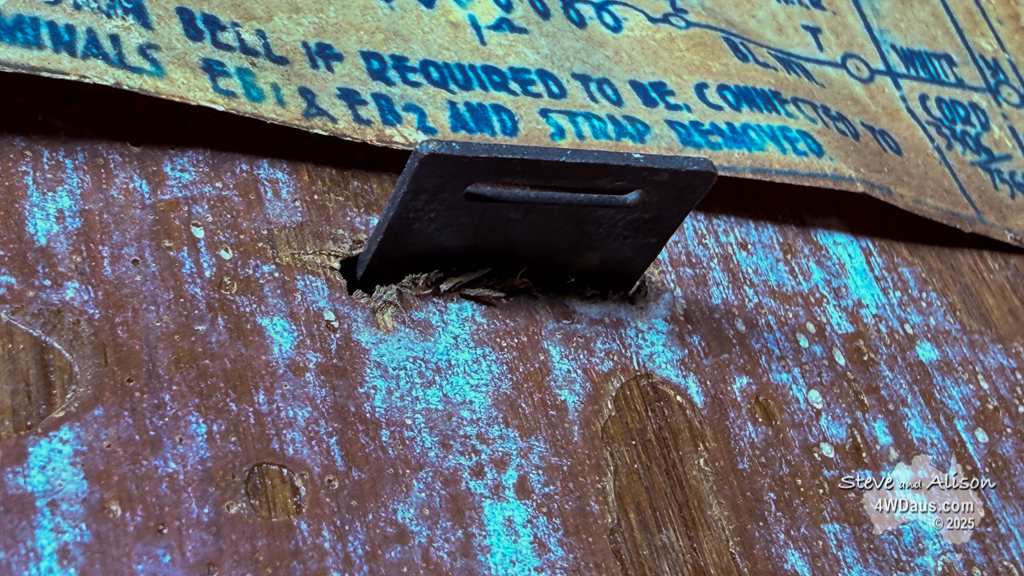
- Front Paper Clip Incomplete
The clip that holds the instruction paper on the angled front board appears incomplete or partially broken.
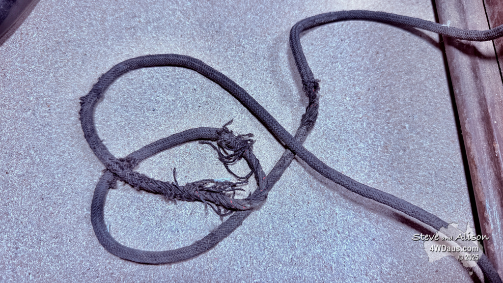
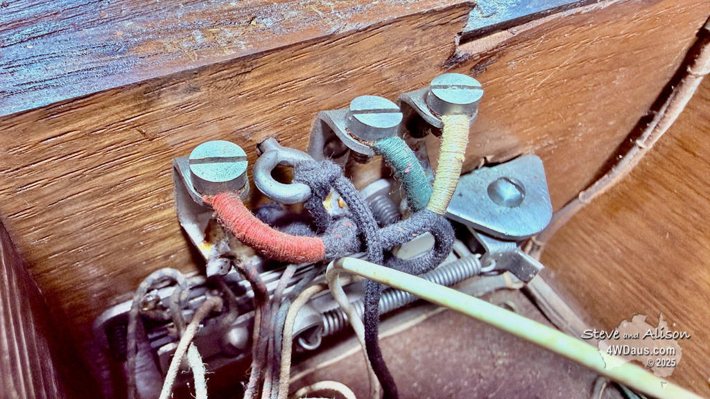
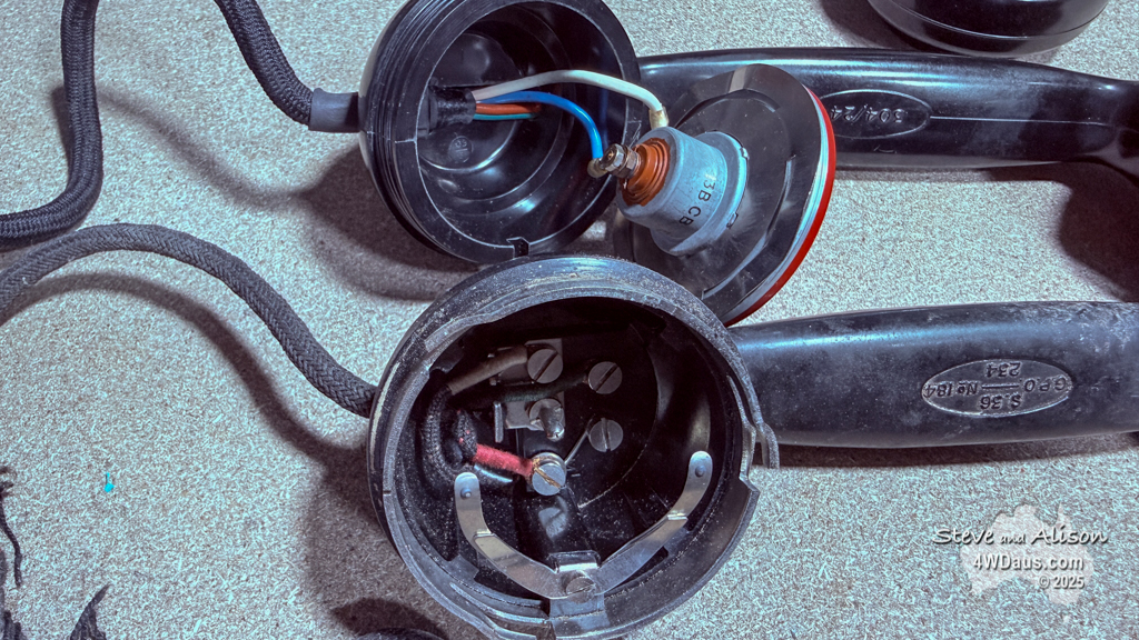
- Receiver Cord Wear
The cloth‑covered receiver cord shows noticeable wear in several places. – Advice from a new friend (John Paskulich – https://oldaustraliantelephones.weebly.com ) is to keep the receiver – but investigate replacing the cord from the new one. It appears the new cord is 4 wires and the older cord is just 3. The reason to not use the newer 304/24 receiver over the older S56 234 is the shape and how it sits in the cradle.
- Warped Back Board Minimal
The timber back board has a slight warp, likely from long‑term storage.
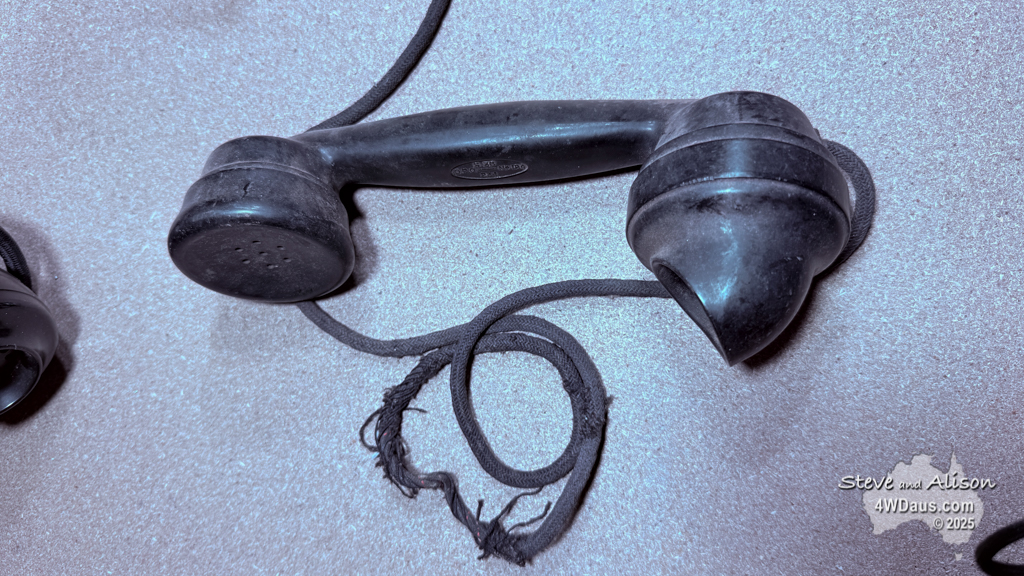
- Bakelite Receiver Condition
The Bakelite handset is moderately marked and will require careful cleaning and polishing.
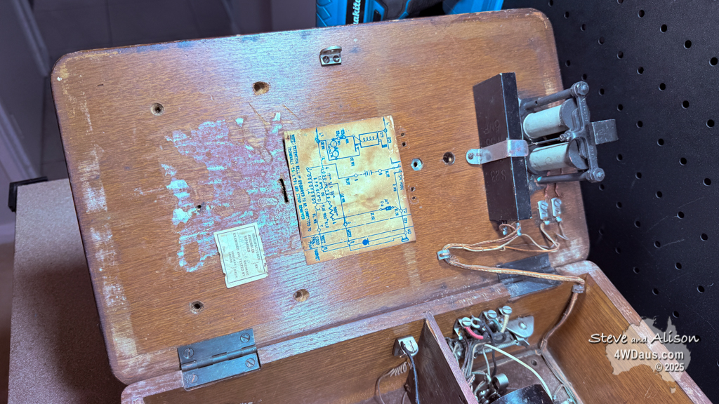
- Missing Internal Diagram
The wiring diagram normally adhered to the inside of the door is missing. A faint adhesive “ghost” remains. This may have been moved higher or there is a second one missing?
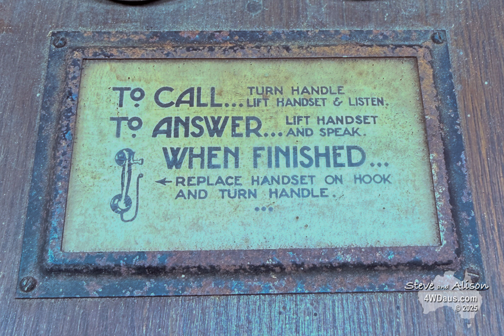
- Front Label Holder Rust
The metal label frame on the front has surface rust.
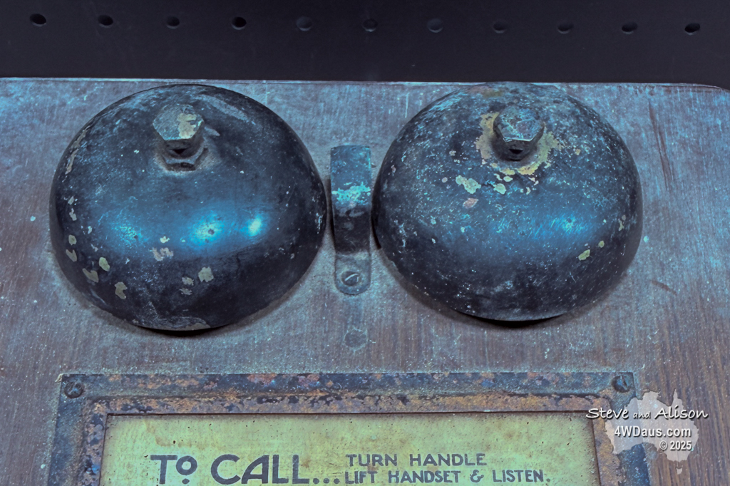
- Brass Bells
The bells themselves are in good condition, with only light internal corrosion and some chipped paint.
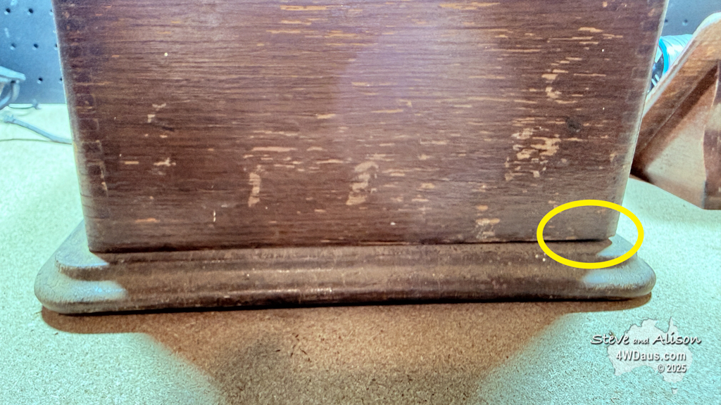
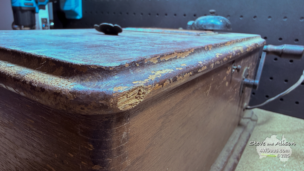
- Small Chip in Front Moulding
A minor chip is present on the front edge of the moulding.
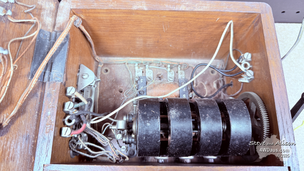
- Electrical and mechanic components
These appears in good condition – there is still oil / grease on the crank components – paint in good condition – will look at just cleaning these components only.
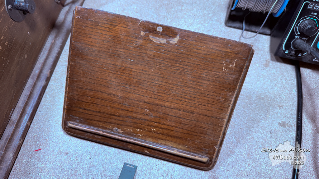
- Front Tray / Writing Shelf
These appears in good condition – it is square and has not warped – it should only request cleanup, and refinishing. The only mark on this appears to be the mark left by the paper clip.
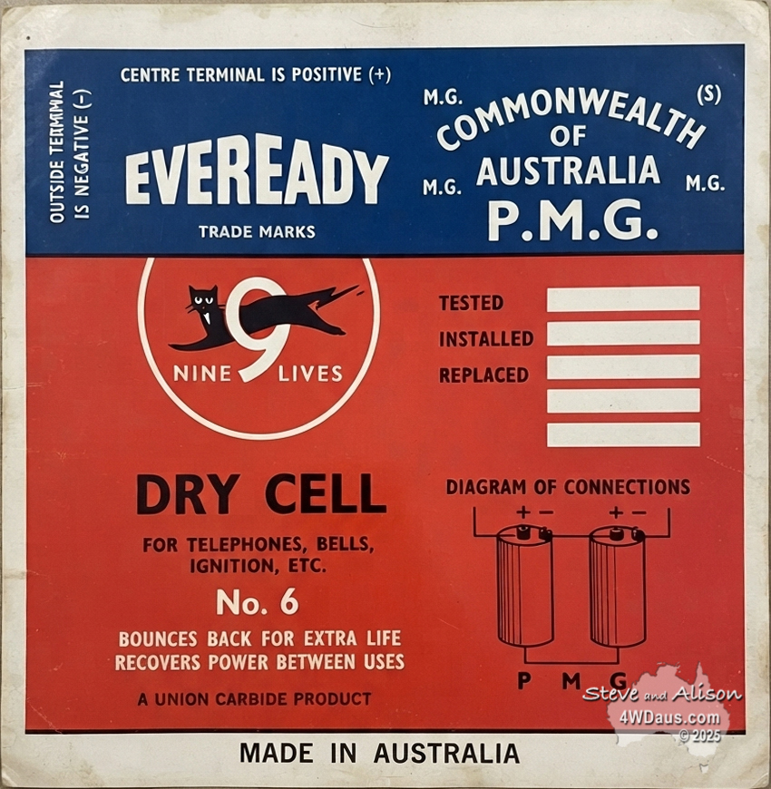
- Display Batteries
To complete the restoration will look at building replica batteries – I have already started to develop the label – I really like this one I am currently working on, I still have a few letting mistakes – but I am on my way. Research found that the knobs (Brass on top) of these No 6 Dry Cells are probably M4 or 5 Knurled Thumb Nuts
Research Findings
A bit of digging has already confirmed several important details about the correct restoration of the Ericsson 35MW/235MW:
Horizontal “To Call” Label — PMG NSW Conversion Practice
When the PMG converted 35MW sets into 235MW handset models, NSW workshops commonly mounted the “To Call / Turn Handle” plate horizontally to cover the original transmitter mounting holes. This practice is well‑documented in NSW collector archives and matches the configuration found on the restoration piece.
Sources:
- Telephone Collectors Australia – Ericsson 35MW/235MW conversions
- Collector restoration notes (archived examples of NSW conversions)
External Metalwork Was Satin Black (Not Matte)
Original PMG specifications and surviving unrestored units show that the bells, crank handle, and external metal fittings were finished in Satin Black. Matte black is a modern repainting error often seen in amateur restorations.
Sources:
- Australian Historic Telephone Society – PMG telephone finishes
- THG UK – Ericsson N2500 finish details
ericsson-n2500-magneto-telephone
Timber Box Should Not Be Varnished
PMG workshop manuals and surviving examples confirm that Ericsson magneto wall phones were not varnished. They were finished with a simple utilitarian oil or shellac coating. Varnish is historically incorrect and was never used by PMG workshops.
Sources:
- Australian Historic Telephone Society – restoration guidelines
- Collector restoration documentation (original finish examples) Also 235mw
Replica Batteries Using 2‑Inch PVC Pipe
Because original PMG dry cells are no longer available, restorers commonly fabricate replica batteries using 2‑inch PVC pipe, painted and labelled to match the original PMG dry cell appearance. This method is widely documented in restoration communities.
Sources:
- Vintage telephone restoration forum – PMG battery replicas
- Eveready Cell Reproduction
- Community restoration examples
Correct Screws Are Slotted, Never Phillips
Phillips screws were not used by the PMG during the service life of the 35MW/235MW. All external and internal screws were slotted, typically brass or blackened steel. Using Phillips screws is considered historically incorrect.
Sources:
- PMG equipment catalogues (screw specifications)
https://www.records.nsw.gov.au/archives/collections
- Australian Historic Telephone Society – hardware standards
https://www.ahts.org.au/telephones/
The Goal
The aim of this project is to restore the Ericsson 235MW to good, historically respectful condition — not over‑restored, not modernised, but preserved as a working example of Australian telecommunications history.
Over the project, we’ll document each step: cleaning, repairs, fabrication of missing parts, and the final reassembly.
A beautiful piece of PMG history is about to come back to life.
PRIMARY / HIGH-VALUE SOURCES
1. PMG Engineering Instruction E2020 — 235MW
PMG E2020 — Magneto Wall Telephones 233MW & 235MW
This is our strongest primary document so far.
2. Australian Post Office 35MW / 135MW documentation
35MW & 135MW — British Ericsson N2500
This establishes the N2500 → PMG 35MW → 135MW → 235MW history.
3. Australian Post Office 235MW
235MW — British Ericsson / PMG
4. Australian Historic Telephone Society
Particularly valuable because its site explicitly lists 233MW/235MW technical material.
5. Australasian Telephone Collectors Society
This is the organisation we’ve been using for the PMG engineering documents.
6. Australia Post history
Good for the overall PMG timeline, but not component-level evidence.
7. NSW State Archives / Museums of History NSW
NSW State Archives collections
Use this for actual archival records, particularly Inverell/NSW PMG records.
8. Telephone Collectors International
Telephone Collectors International
Potentially very useful for original Ericsson documentation.
Disassembly
Every restoration project has its first decisive moment, and today the Ericsson 35MW/235MW finally began its journey back to life. The goal was simple: break the instrument down into its major assemblies so each component can be rejuvenated piece by piece. As expected with century‑old PMG equipment, the process was part detective work, part careful engineering.
Removing the Magneto Handle — The First Challenge
Research offered surprisingly little guidance on how to remove the magneto winder handle. After probing the interior with a torch, a small retaining screw was finally spotted deep inside the magneto on the crank shaft. Loosening it should have allowed the shaft and handle to slide free — but before committing, we took a more cautious approach.
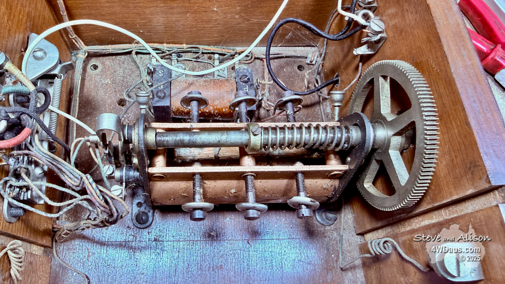
To ensure springs, washers, and orientation‑critical parts weren’t disturbed, the internal shelf (bearing the original “British Ericsson” branding) was slid out first. This provided access to the side of the magneto and allowed the four horseshoe magnets to be loosened. Care was taken not to swap their N/S polarity, which is essential for correct generator operation.
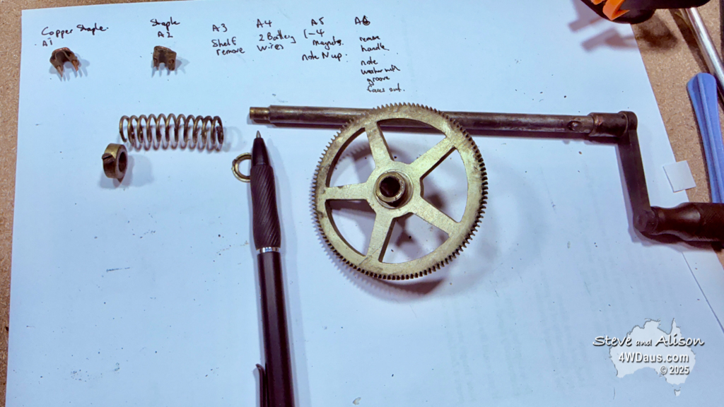
Once the magnets were free, the shaft could be removed — revealing an important discovery: one of the washers was single‑sided, meaning its orientation matters. A lucky catch. It also confirmed that this magneto winder differs from many others; contrary to advice found online, the handle cannot be removed from the shaft externally. The entire assembly must be withdrawn from inside the case.
Systematic Breakdown of the Instrument
With the magneto freed, the rest of the disassembly proceeded methodically:
- Internal shelf removed
- Magneto disassembled; shaft and handle withdrawn
- Magneto wiring disconnected and magneto unbolted from baseboard
- Magneto winder box trim removed
- Battery terminals removed
- Handset cord and handset detached
- Four copper/brass staples removed from wiring loom
- Bell assembly removed
- Front “To Call” label unscrewed
- Bell wire terminals removed
- A mysterious black box detached
- Hinges removed (two of the six screws noted as longer)
- Latch removed
- Receiver hook removed
- Receiver switch unbolted from case
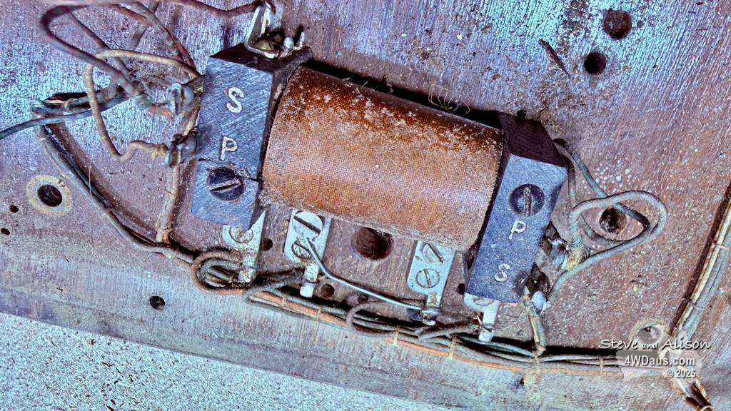
- Component marked S and P removed, kept attached to its wiring loom
- Final wiring loom section released (four screw mounts) and loom removed entirely
The Circuit Diagram Label — A Delicate Operation
The last remaining internal component is the printed circuit diagram adhered to the inside of the door. It appears fragile, and removal without damage will require more research. For now, it has been left untouched overnight while we seek advice on safe extraction techniques.
Community Input
A post on the Historic Telephones Western Australia Facebook group yielded helpful responses. Members confirmed that the front paper clip assembly is indeed incomplete — a rear clip piece is missing. Additional advice has been requested regarding safe removal of the circuit diagram label.
End of Day Status
By the end of the session, the restoration piece is now reduced to:
- Two plastic boxes of components and wiring
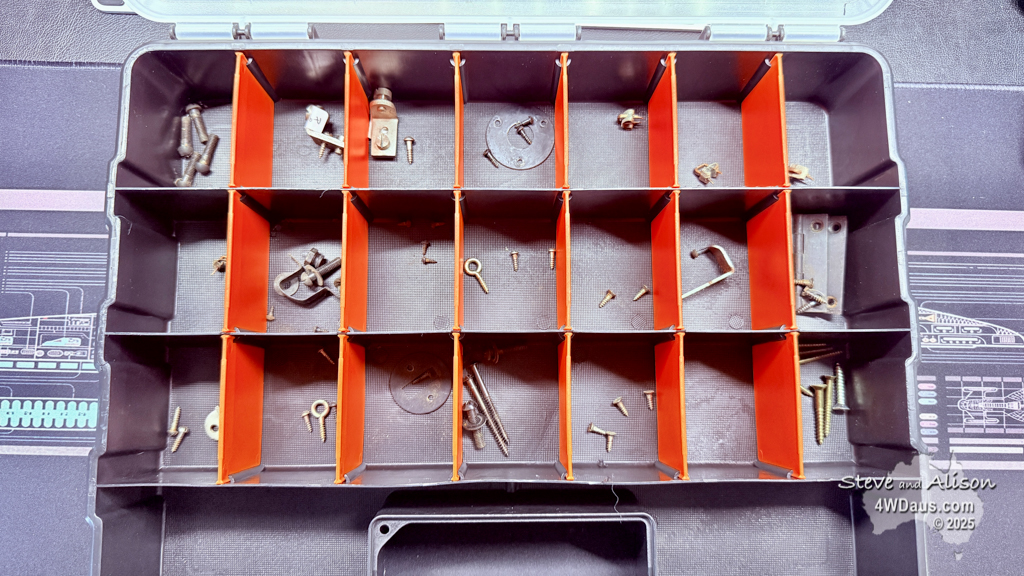
- One dedicated compartment box containing screws, washers, springs, and small hardware, all carefully separated and labelled
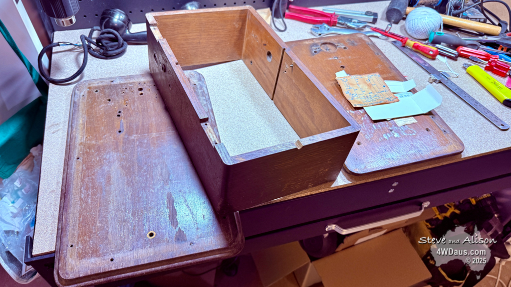
- The wooden case in three parts
- A fully removed wiring loom
- A clear path forward for cleaning, cataloguing, and restoration
The project is officially underway.